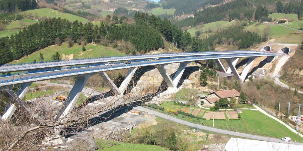
The Arbizelai Viaduct is to be found in the outskirts of Arrasate-Mondragón and crosses, albeit with a pronounced skew, the River Deba Valley and the south access link to Mondragón.
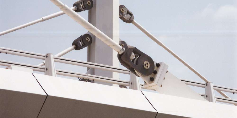
The total length of the viaduct is 408.72m broken down into six spans of 37.44 + 53.04 + 59.28 + 59.28 + 140.4 + 59.28m. To solve the main span it was projected to stay this and its adjacent spans with cable stays situated in the axis of the bridge on two composite pylons placed in the central reservation.
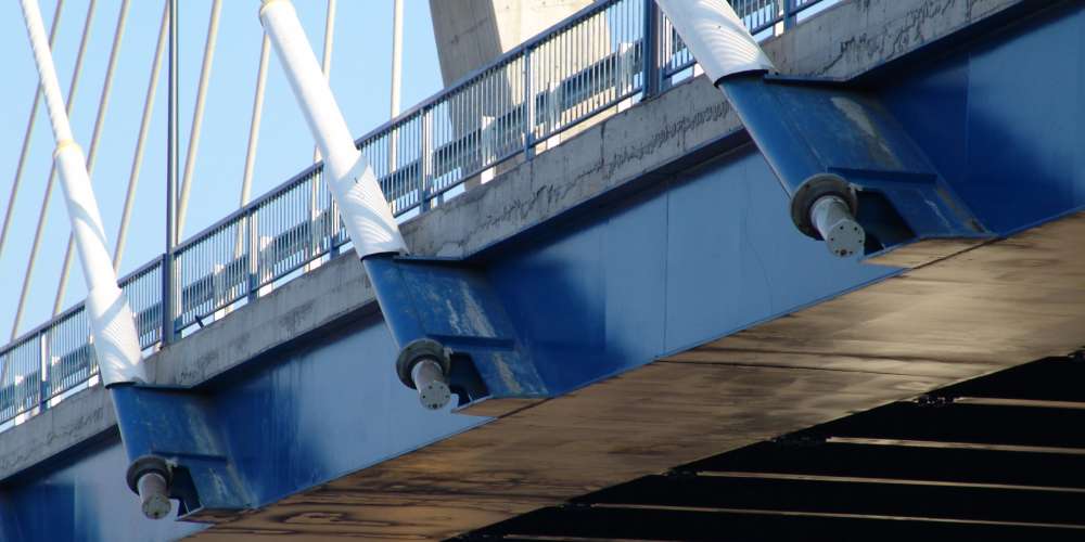
The deck is set 25.0m above the valley basin and is solved with a standard deck type for both carriageways and has a constant 2.65m depth. It is a mixed, two-cell, trapezoidal-shaped box girder with a lower width of 9.0m and an upper concrete slab which varies in width between 25.20m and 27.40m. It also has lateral cantilevers which are supported on diagonally placed steel struts every 3.12m which begin at the lower edge of the box girder and act as support to the concrete slab on the cantilever edge.
The piers have a variable cross-section formed from a single shaft. The section is rectangular at its base and then tapers outwards from 2.70m to 10.10m at its head. The pier foundations are direct onto the bedrock employing concrete footings.
Both abutments are closed. Abutment 1 has a variable height dependent on the banking, with a single foundation level, having an average height of around 11.0m and a constant depth of 1.50m. The solution adopted for abutment 2, given the difference between the edges of the deck, offers three foundation levels, with heights of approximately 18.5m on the left to around 10.0m on the left. The depth varies between 2.5m and 1.5m. In the area which coincides with the axis of the structure a 2.0m wide buttress has been placed where the last cables of the sixth span are anchored.
Construction Process.
Once the piers and the abutments of the viaduct have been constructed, the box girder shall be pushed across from either side of the abutments. From abutment 1, spans 1,2,3,4 and half of 5 (stayed span) shall be pushed and the rest, spans 6 and half of 5 shall be pushed from abutment 2.During this phase, four provisional stays shall be placed, which shall be disassembled, once both parts of the deck have been joined in the centre of the stayed-span.

 We use cookies by Google Analytics for statistical purposes.