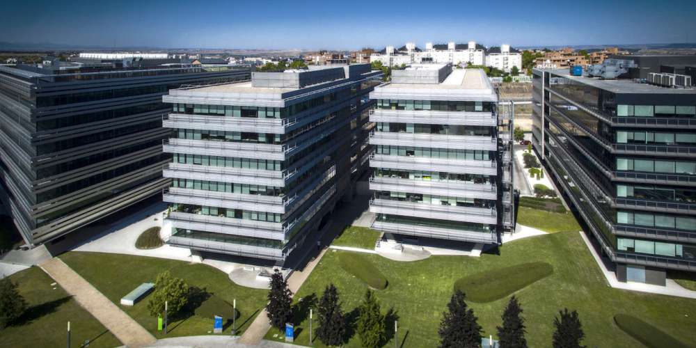
The building is composed of 5 storeys above grade, practically rectangular in shape, 76.0m x 17.5m, and covers a surface area of 1,530m2. There are 4 levels below grade. The dimensions of these floors are approximately 95.0m x 51.0m covering a total surface area of 4,900m2.
Its façade is composed of an external skin made up of a myriad of different types of glass which are held together on a metal framework, and rises over the M40 motorway offering a magnificent hallmark of its identity. The building is interconnected via a series of gangways set at different levels.
The horizontal structure is completely executed employing grid slabs. It would be worth differentiating between the grid slabs on the typical floor, ground floor and basement -1, whose characteristics are as follows:
− TYPICAL FLOOR: Post-stressed grid slab 40+10 (cm), nerve width 18 cm, interaxial distance between nerves 86 cm. Spans 16.10 m in N-S direction and 8.10 m in E-W direction.
− GROUND FLOOR: Grid slabs 35+15 (cm), nerve width 16 cm, interaxial distance between nerves 84 cm. Maximum spans 8.98.
− BASEMENT FLOOR -1: Grid slabs 25+10 (cm), nerve width 16 cm, interaxial distance between nerves 84 cm. Maximum spans 8.98.
This triple typology in the slab type has been motivated in the case of the typical floor type, due to the large spans to be covered (16.10m) between columns, whilst the difference between the typologies in the ground and basement -1 floors is due to the high existing loads imposed in the first mentioned, caused by the difference in levels between the upper slab level and the finished floor which are solved with screeds and fills, as is also the case in the access area for the fire brigade. The retaining walls employed in the excavation are 0.50m thick continuous diaphragm walls. During the excavation process two levels of provisional anchorage have been foreseen.
The vertical structure has been solved employing columns and walls situated in the lift wells, given that the latter are well situated for this function. The vertical loads are transmitted to the foundations through the columns and the horizontal loads through the aforementioned wells.
The columns are 0.90m x 0.50m in size with the shorter side running parallel to the façade. These columns between ground and first floor are joined two by two and are set back, so obtaining a 0.80m x 1.70m column down to the foundation unit.
To solve this setting back between ground and first floor, the columns are tapered and the edges are rounded off.
On floors basement -1, basement -2 and basement -3, apart from the columns which support the floors above grade, there are also round, square and rectangular columns.
The four walls situated in the vertical communication shafts are made of reinforced concrete and are a constant 0.30m thick. They are C-shaped on plan.
It has not been deemed necessary to employ expansion joints in the floors, given that the corresponding dimensions are relatively moderate so as to fear possible structural effects in the slabs or columns due to thermal or rheological effects.

 We use cookies by Google Analytics for statistical purposes.